
Tool wear - mechanisms & countermeasures
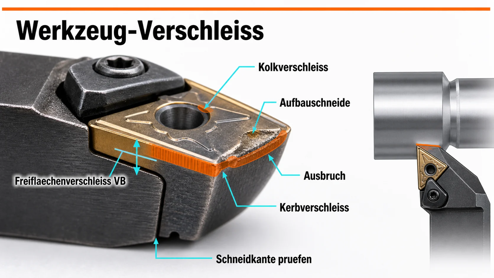
8 typical wear types on cutting tools with causes, countermeasures and identifying features.

ISO 3685 defines VB = 0,3 mm Flank wear as tool life end in roughing, VB = 0,15 mm when finishing. Regular visual inspection = simplest tool-life prediction.
Built-up edge (BUE)
Material particles weld to the cutting edge under pressure and form an unstable „pseudo cutting edge“. This periodically breaks off and tears chips of the coating away with it. Typical with tough low-alloy materials and too low cutting speed.
Causes
- Cutting speed too low (below critical vc)
- Rake angle too small → high friction pressure
- Coolant does not reach the cutting edge
- Material tends to adhesion sticking (unalloyed steel, aluminium)
Countermeasures
- Increase vc significantly (above 80–120 m/min for steel)
- More positive rake angle or polished rake face
- High-pressure coolant (40–70 bar) directly at the cutting edge
- Coating with low friction coefficient (TiAlN, AlCrN, DLC)
Crater wear
A trough-shaped depression („crater“) on the rake face, a few tenths behind the cutting edge. Arises from chemical dissolution of the tool material into the chip - temperature-related. Sooner or later breaks out the cutting edge.
Causes
- Cutting speed too high (heat > 1000 °C)
- Wrong coating (TiN on steel instead of Al₂O₃)
- Too little cooling
- Highly abrasive materials (Si-bearing aluminium)
Countermeasures
- reduce vc by 15–25 %
- Choose Al₂O₃ or Ti(C,N) coating (heat-stable)
- Increase coolant concentration to 8–10 %
- Optimize the chip breaker (shorter chip ejection → less cratering)
Flank wear (VB)
Uniform wear on the flank below the cutting edge. Measured with VB (flank wear land width). Standard tool-life criterion per ISO 3685 - VB = 0.3 mm is considered end of tool life in roughing, VB = 0.15 mm in finishing.
Causes
- Normal abrasive wear from the workpiece
- Hard inclusions in the material (carbides, oxides)
- Feed too low → no defined chip
- Wrong tool material for the hardness (HSS at > 30 HRC)
Countermeasures
- Harder tool material: solid carbide, cermet, ceramic
- Coating with high hardness (Al₂O₃, c-BN)
- Increase feed (fz/fn by 20–30 %)
- Detect end of tool life in time (VB measurement)
Notch wear
Locally sharply increased wear exactly where the cutting edge leaves the workpiece surface (chip exit zone). Typical with hard material skins (mill scale, cast skin, glass-hard skin).
Causes
- Workpiece surface heavily work-hardened or oxidized
- Depth of cut ap too constant → same spot always loaded
- Materials prone to work hardening (austenitic steel, Inconel)
- Negative corner radius of the tool
Countermeasures
- Vary ap: angled approach or multiple ap steps
- Larger corner radius (distributes the load)
- Coating with high toughness (PVD-TiAlN)
- Remove first skins with a dedicated roughing tool
Thermal cracks (Comb / Thermal Cracking)
„Comb cracks“ running perpendicular to the cutting edge from cyclic heating and cooling - milling with coolant is the classic case. The cracks grow until the cutting edge breaks up.
Causes
- Change cutting / non-cutting during milling
- Coolant on the hot cutting edge → thermal shock
- Very high vc (> 250 m/min) in interrupted cutting
- Brittle tool material (ceramic, c-BN)
Countermeasures
- Mill DRY if possible (no shock loads)
- If cooling is needed: only for chip flushing, not on the cutting edge
- Reduce vc by 15–20 % for crack-sensitive tool materials
- Tougher tool material grade with better thermal shock resistance
Breakouts (chipping)
Small chips out of the cutting edge, often several 0.1 mm in size. The cause is usually a mechanical shock - either on entry or from hard inclusions in the material.
Causes
- Entry impact too harsh (full engagement profile immediately)
- Feed too high → cutting edge overloaded
- Brittle tool material too brittle for interrupted cut.
- Existing impact marks on the workpiece (voids, inclusions)
Countermeasures
- Smooth entry: arc lead-in instead of linear entry
- Reduce feed by 20 % (at least on the first cuts)
- Choose a tougher grade (roughing before finishing)
- Apply a chamfer to the cutting edge (chamfer for entry protection)
Plastic deformation
The cutting edge gives way under pressure and heat - it „slips“ slightly. Often recognizable by a bulged cutting edge. Critical with VHM, because crater wear then progresses extremely quickly.
Causes
- Depth of cut ap and feed simultaneously too high
- Tool material too soft for the thermal load
- Material very hard (> 45 HRC) at normal cutting values
- Coating too thin / not thermally insulating
Countermeasures
- Harder tool material: K10–K20 substrate, Al₂O₃ coating
- Spec. cutting data for hard machining (vc lower, ap smaller)
- Thermal-insulating thick Al₂O₃ top coating (CVD)
- Hard machining requires dedicated grades (e.g. Sandvik CB7050)
Diffusion wear
Chemical dissolution of the tool material into the chip at high temperatures. Iron dissolves tungsten carbide - the main problem in VHM machining of titanium and nickel-based alloys.
Causes
- Very high temperatures at the cutting edge (> 900 °C)
- Chemically reactive materials (Ti, Ni alloys)
- Cutting speed too high
- Coating missing or worn
Countermeasures
- reduce vc significantly (Ti6Al4V: vc < 60 m/min)
- Diffusion barrier through TiAlN or AlCrN coating
- When milling: high-pressure internal coolant (70+ bar)
- PCD tool material for reactive materials where possible
Wear classification per ISO 3685 (tool-life testing with single-point turning tools) and VDI 3324 (wear behaviour). Schematic drawings and descriptions: own representation based on the generally accepted wear classification. For recurring wear patterns: share the image with the service technician of your tool supplier.
Note: all cutting and material values are guide values. The tool or machine manufacturer's recommendations are decisive.
The calculator also runs in the workshop without a connection: app and desktop version