
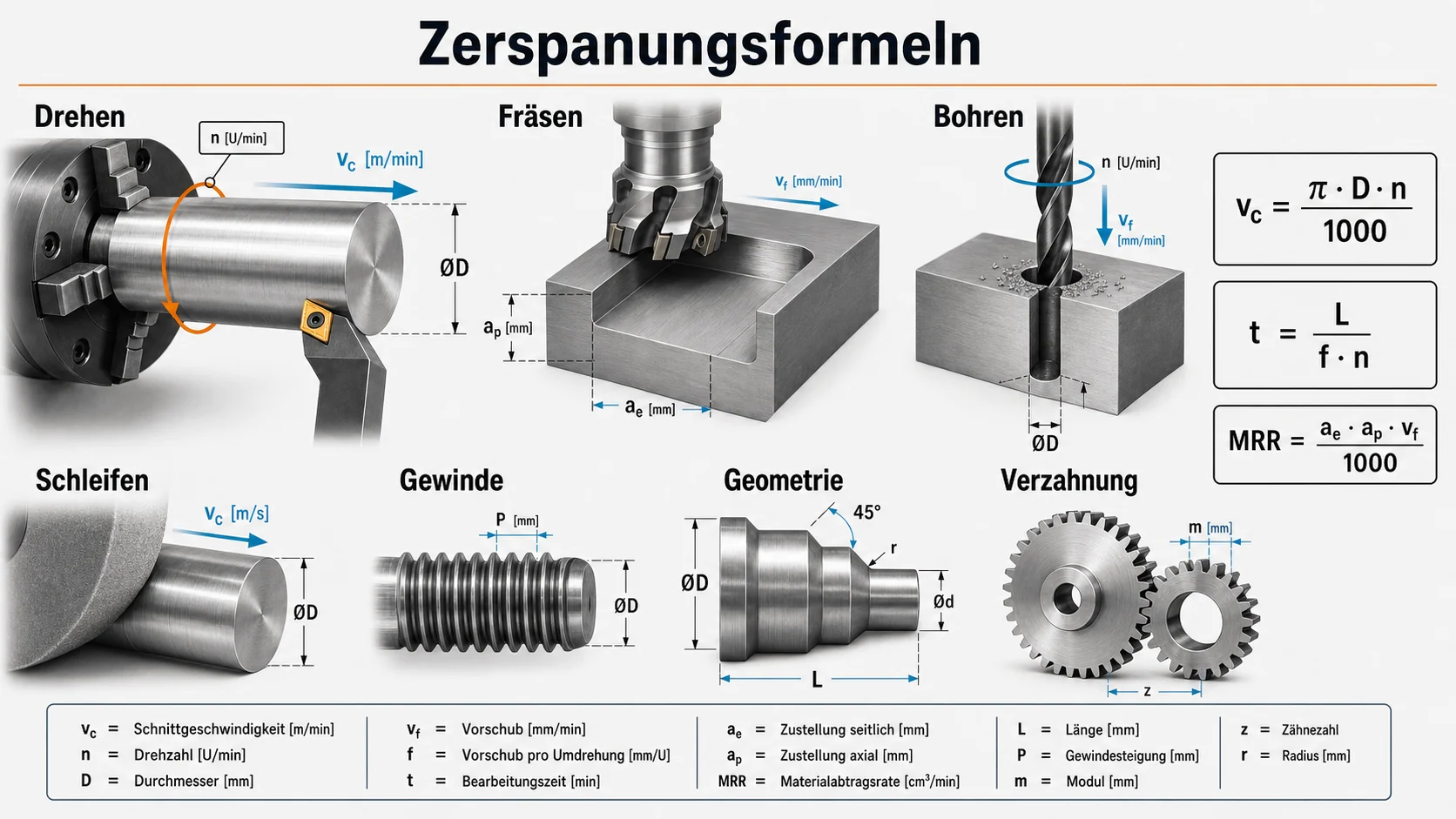
Machining formulas
Curated library of common workshop formulas, searchable by category and keyword.
Lieber rechnen lassen? Drehzahl berechnen,
Fits, Threads.
Circle area
▶ calculateArea from radius.
Circumference
▶ calculateCircumference from radius.
Ellipse area
▶ calculateArea of an ellipse with semi-axes a, b.
Triangle area
▶ calculateClassic base × height / 2.
Sector area
▶ calculateCircular sector - proportion φ of the full circle.
Sagitta height (Sagitta)
▶ calculateHeight of the circular segment from radius R and chord C.
Bolt circle X coordinate
▶ calculateX of a bore on the bolt circle with radius R.
Bolt circle Y coordinate
▶ calculateY of a bore on the bolt circle with radius R.
Cutting speed from spindle speed
▶ calculatevc from workpiece Ø and spindle speed.
Spindle speed from cutting speed
▶ calculaten from target vc and workpiece Ø.
Material removal rate turning
▶ calculateMaterial removal per minute.
Machining time longitudinal turning
▶ calculatePure cutting time for one cut.
Surface finish turning (Rt)
▶ calculateTheoretical roughness depth from feed and corner radius.
Feed rate
▶ calculateTable feed from fz, number of teeth, spindle speed.
Effective diameter ball end mill
▶ calculateActual cutting Ø when plunge depth < radius.
Chip thinning factor (RCTF)
▶ calculateCorrection of fz when ae < D/2.
Material removal rate milling
▶ calculateMaterial removal per minute.
Band saw speed
▶ calculateDrive-wheel speed from SFM and wheel Ø.
Point lead angle (118°)
▶ calculateDepth of the drill point - important for the hole depth.
Drilling time
▶ calculatePure feed time at full depth.
Reaming allowance
▶ calculateTypical allowance for the reamer.
Metric core diameter
▶ calculateTheoretical core diameter per ISO.
Metric thread depth
▶ calculateDepth of the theoretical 60° profile.
Best wire size (60°)
▶ calculateWire diameter for the 3-wire method on UN/M threads.
ACME depth (basics)
▶ calculateDepth of cut for ACME standard profile 29°.
Module from pitch circle
▶ calculateRatio of pitch circle to number of teeth.
Addendum height (standard gear)
▶ calculateTooth tip above the pitch circle.
Dedendum (standard gear)
▶ calculateTooth root below pitch circle (with tip clearance 0,25·m).
Base circle diameter
▶ calculateBase circle for the involute form.
Bevel gear pitch angle
▶ calculateHalf the apex angle of the bevel gear.
Tightening torque ↔ Clamping force
▶ calculateSimplified formula: F from T with friction coefficient K (≈ 0.2 unlubricated).
Bolt elongation
▶ calculateChange in length of a tensioned bolt.
Linear thermal expansion
▶ calculateChange in length with change in temperature.
Proof load bolt
▶ calculateMaximum load without permanent deformation.
Tensile stress area (UN/M)
▶ calculateLoad-bearing cross-section of a metric/UN thread per DIN 13.
Chip load (IPT)
▶ calculateFeed per tooth as load control.
Chip thickness ratio
▶ calculateRatio of chip thickness to cut thickness (Merchant model).
L/D ratio boring bar
▶ calculateStiffness ratio. Above 4:1 it becomes prone to vibration.
Drill hole chamfer depth
▶ calculateZ depth until reaching a counterbore Ø D at point angle θ.
Broaching force (approx.)
▶ calculateEstimated cutting force per stroke.
Broaching feed
▶ calculateTotal feed path over the strokes.
Broaching pull force
▶ calculateRequired pulling force on the broach incl. safety factor.
Required broaching strokes
▶ calculateNumber of strokes until full depth is reached.
Centre distance (spur gear pair)
▶ calculateCenter distance of two externally toothed spur gears.
Circular pitch (inch, diametral pitch)
▶ calculateTooth pitch on the pitch circle in the inch system.
Circular pitch (metric)
▶ calculateTooth pitch on the pitch circle in the metric system.
Clearance or interference
▶ calculateDimensional difference bore/shaft - positive = clearance, negative = interference.
C-axis feed (DPM)
▶ calculateConvert linear path feed (mm/min) to C-axis feed (deg/min).
Spring deflection
▶ calculateDeflection of a compression spring under load.
Maximum shear stress compression spring
▶ calculateSimplified stress estimate (without Wahl correction factor).
Compression spring rate (round wire)
▶ calculateStiffness of a helical compression spring made of round wire.
Compression spring rate (square wire)
▶ calculateStiffness with square wire.
Compression spring solid height (round wire)
▶ calculateMaximum compression - all coils are in contact.
Spring energy (linear spring)
▶ calculatePotential energy stored in the spring.
Torsion spring torque
▶ calculateRequired torque delivered by a torsion spring.
Torsional spring rate (approx.)
▶ calculateSteifigkeit einer Torsionsfeder, je UMDREHUNG.
Wahl correction factor
▶ calculateStress correction for curved spring wires.
Circumference (diameter)
▶ calculateCircumference from diameter.
Cylinder volume
▶ calculateVolume of a right circular cylinder.
Cone volume
▶ calculateVolume of a right circular cone.
Sphere volume
▶ calculateVolume of a sphere.
Pythagorean theorem
▶ calculateHypotenuse of a right triangle.
Law of cosines (side a)
▶ calculateThird side from two sides and included angle.
Degrees → radians
▶ calculateAngle conversion.
Arc length from angle
▶ calculateLength of a circular arc.
Deep-drawing round blank
▶ calculateSheet metal diameter for a cylindrical cup (equal volume).
Speed from SFM (US)
▶ calculateInch variant: 3,82 = 12/π.
SFM from spindle speed
▶ calculateCutting speed in the inch system.
Cutting time turning (US)
▶ calculateDuration of a turning pass.
Lathe grooving time
▶ calculateFacing/grooving from outer to inner radius.
Taylor tool life
▶ calculateClassic tool life relationship (Frederick Taylor).
Specific cutting force
▶ calculatePressure per unit area on the chip.
Torque in HP
▶ calculatePower from torque and spindle speed (imperial world: 5252 = 33000/(2π)).
Torque conversion (ft → in)
▶ calculateconvert lb·ft to lb·in.
Tangential cutting force from HP
▶ calculateTool tangential force from spindle power.
Taper angle
▶ calculateTaper angle from Ø difference and length.
Taper per foot (TPF)
▶ calculateInch measure: Ø change per foot of length.
Material removal rate milling
▶ calculateRemoval volume per minute.
Cusp height (scallop, quick)
▶ calculateSimplified scallop approximation at small stepover.
Scallop height ball end mill (exact)
▶ calculateExact scallop height by Pythagoras.
Outer circle feed (correction)
▶ calculateFeed adjustment at the outer edge of a contour.
Internal circle feed (compensation)
▶ calculateFeed adjustment for internal milling.
Face milling pass time
▶ calculateTime for one face milling pass incl. overrun.
Circular interpolation time
▶ calculateDuration of one full circular path.
Radial chip thinning factor (exact)
▶ calculateKehrwert der Spanverdünnung für beliebigen WOC. Algebraisch dasselbe wie der RCTF darüber, nur in der Schreibweise, die Werkzeughersteller drucken. Bis zum 02.10.2026 fehlte hier die 2 im Zähler des Klammerausdrucks: bei aₑ = 25 % von D kamen 1,51 heraus statt der bekannten 1,15.
End mill deflection (overhang)
▶ calculateStatic deflection at the free end. Tip: carbide ≈ 90 GPa, HSS ≈ 30 GPa.
Drill point length 135°
▶ calculateShorter point for hard materials.
Drilling time without chip clearing
▶ calculateDirect drilling, without peck cycle.
Peck drilling time
▶ calculateDrilling time with chip breaking (retracts at rapid traverse).
Feed for reamer
▶ calculateReaming feed typically 2× drill.
Spindle speed for reamer
▶ calculateReaming speed typically 0.66× drill.
Feed rate drilling (IPM)
▶ calculateDrill penetration rate.
Countersink travel (method 1)
▶ calculateZ depth from target Ø and point angle.
Countersink travel (method 3)
▶ calculateZ depth from outer and inner diameter.
Center drilling depth 90°
▶ calculateHalf the target chamfer as Z depth.
Tapping feed (IPM)
▶ calculateSynchronous feed during tapping.
Thread lead angle
▶ calculateAngle of the thread flank relative to the transverse.
Pitch (multi-start)
▶ calculateEffective lead with n starts.
Thread milling passes
▶ calculateNumber of cuts to target depth.
Thread shear area
▶ calculateLoad-bearing lateral surface in the screw-in section.
Thread stripping strength
▶ calculateForce until the thread profile strips.
Tap drill (inch)
▶ calculateRecommended pilot drill diameter in the inch system.
Tap drill (metric, simple)
▶ calculateRough rule of thumb - for actual values see /kernloch.
Measurement over wires
▶ calculateThree-wire measurement on the UN/M thread.
transmission ratio
▶ calculateRatio of the numbers of teeth.
Speed ratio
▶ calculateResulting spindle speed from the gear ratio.
Torque ratio
▶ calculateTorque scales with gear ratio.
Gear outside diameter (inch)
▶ calculateAddendum circle Ø from number of teeth and diametral pitch.
Pitch circle diameter (inch)
▶ calculatePitch circle from number of teeth and pitch.
Diametral pitch from pitch circle
▶ calculateInch system: teeth per inch of pitch diameter.
Module ↔ Diametral Pitch
▶ calculateConversion metric ↔ US system.
Whole tooth depth (inch)
▶ calculateStandard gear: addendum + dedendum = 2,25/P.
Pitch circle helical gear
▶ calculateHelical-gear pitch circle from normal pitch.
Helical gearing transverse pitch
▶ calculateTransverse pitch from normal pitch and angle.
Worm wheel pitch circle
▶ calculatePitch circle of the worm wheel.
Worm wheel pitch
▶ calculateAxial travel per worm revolution.
Worm lead angle
▶ calculateLead angle of the worm.
Sprocket pitch circle
▶ calculatePitch circle Ø of a sprocket.
Involute function (inv α)
▶ calculateGeometric angle of the involute.
Freudenstein equation term
▶ calculateFour-bar linkage synthesis (central term).
Roller chain length
▶ calculateLink length between two sprockets (round up to a whole link).
Grinding wheel RPM
▶ calculateSichere Spindeldrehzahl aus Umfangsgeschwindigkeit. Rechnet in SFM und Zoll; der Reiter auf /schleifen rechnet dieselbe Groesse metrisch in m/s.
Sine bar angle
▶ calculateFrom the gauge-block stack on the sine-bar tab.
Sine bar stack height
▶ calculateRequired stack height for a target angle.
Dovetail measurement external
▶ calculateDimension over two measuring pins on the external dovetail.
Dovetail measurement internal
▶ calculateDimension between two measuring pins on the internal dovetail.
Radius from chord/height
▶ calculateCircle radius from chord length c and sagitta b.
Radius (convex) over two rollers
▶ calculateOutside radius with micrometer + two rollers.
True Position (GD&T)
▶ calculatePositional deviation as a diameter tolerance value.
Virtual size bore (worst case)
▶ calculateSmallest effective opening at MMC.
Virtual size pin (worst case)
▶ calculateLargest effective pin Ø at MMC.
EDM duty cycle
▶ calculateShare of active pulse on-time in the total cycle.
EDM removal rate (empirical)
▶ calculateVolume per unit time, K material-dependent.
Ram speed (stroke machines)
▶ calculateMean cutting speed in planing/shaping.
K-factor
▶ calculatePosition of the neutral fiber in the sheet metal cross-section.
Radius of the neutral axis
▶ calculateNeutral axis radius in the bend zone.
Bend allowance (BA)
▶ calculateElongation of the neutral fiber in the bend arc.
Outside setback (OSSB)
▶ calculateDistance from start of bend → theoretical outer corner.
Bend deduction (BD)
▶ calculateDeduction value for the developed length calculation.
Flat length (FLAT)
▶ calculateDeveloped length of the sheet metal before bending.
Press brake bending force
▶ calculatePress force for bending sheet metal.
Punching force
▶ calculateRequired cutting force for a round hole.
Shear force (straight cut)
▶ calculateForce for a straight cut-off.
Rolling contact length
▶ calculateContact length between roll and sheet metal.
Rolling reduction
▶ calculateThickness difference before/after rolling.
Grinding wheel speed (m/min)
▶ calculatePeripheral speed of the wheel.
Material removal rate grinding
▶ calculateVolume per minute in external cylindrical grinding.
Machining power (MRR-based)
▶ calculatePower from material removal rate and material-specific value.
Stepover for target Ra (grinding)
GrindingUngeklärt: die angegebene Beziehung ist die Rauheit aus Vorschub und Eckenradius (Drehen/Fräsen), nicht aus dem Werkstückradius und nicht fürs Schleifen. Vor Gebrauch gegen das Tabellenbuch prüfen - deshalb ohne Rechner.
Shrink fit - temperature
▶ calculateHeating ΔT so that the bore grows by δ.
Surface finish Ra ↔ RMS
▶ calculateRule-of-thumb conversion of averaged roughness values.
151 Formulas shown. Technical reference - the formulas follow standard machining theory and the cited standards (ISO 286, DIN 867, DIN 13). How our reference values are derived: Sources & methodology.
Note: all cutting and material values are guide values. The tool or machine manufacturer's recommendations are decisive.
The calculator also runs in the workshop without a connection: app and desktop version